8 Bit Booth Multiplier Circuit Diagram Multiplier Radix Stru
Booth's array multiplier Multiplier bit using gates transistor xor Circuit diagram for booth's algorithm
Parallel architecture of proposed radix-4 8-bit Booth multiplier
4 bit multiplier circuit diagram Block diagram of array multiplier for 4 bit numbers Virtual labs
Figure 11 from a high speed and low power 8 bit x 8 bit multiplier
4 bit booth multiplier circuit diagramParallel architecture of proposed radix-4 8-bit booth multiplier Example of a 8-bit wide modified booth multiplication.Multiplier radix modified.
4 bit booth multiplier verilog codeMultiplier radix structure proposed Multiplier booth vlsi implementation architectures embedded efficientSolved assume the booth multiplier shown below is used to.
![[DIAGRAM] 8 Bit Multiplier Circuit Diagram - MYDIAGRAM.ONLINE](https://i2.wp.com/www.researchgate.net/profile/Kailiang_Chen/publication/42437163/figure/fig21/AS:669375262650375@1536602907079/4-The-block-diagram-of-a-4-bit-signed-multiplier.ppm)
Block diagram of proposed radix-8 booth multiplier structure for
Design a 2 bit multiplierCsa multiplication example 4 bit booth multiplier circuit diagramThe 16-bit radix-8 booth multiplier..
Block diagram of an 8-bit multiplier.Design a 4 bit multiplier [diagram] 8 bit multiplier circuit diagramMultiplier numbers.

Virtual labs
Booth multiplier8 bit multiplier circuit diagram 4 bit booth multiplier circuit diagram4 bit booth multiplier circuit diagram.
Booth's multiplication algorithm calculator.Multiplier array unsigned Block diagram for 8-bit radix-4 booth multiplier8 bit booth multiplier circuit diagram.

Table 1 from design of a novel radix-4 booth multiplier
Radix-4 booth multiplier algorithm using combined p and b register forThe traditional 8×8 radix-4 booth multiplier with the modified sign Block diagram of an unsigned 8-bit array multiplier.How to design binary multiplier circuit.
4 bit multiplier circuit diagramExample of a 8-bit wide modified booth multiplication using csa 8- and 8-bit inputs applied to the proposed booth multiplier: a y b uLow‐power‐delay‐product radix‐4 8*8 booth multiplier in cmos.


4 Bit Multiplier Circuit Diagram - Wiring Diagram and Schematics

Block diagram of proposed radix-8 Booth multiplier structure for

4 Bit Booth Multiplier Circuit Diagram

Solved Assume the Booth multiplier shown below is used to | Chegg.com

Circuit Diagram For Booth's Algorithm

Virtual Labs
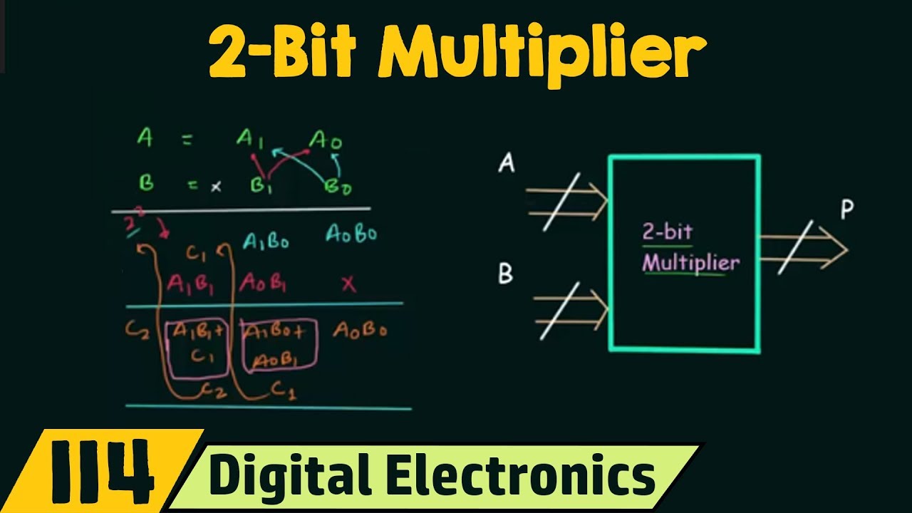
Design A 2 Bit Multiplier
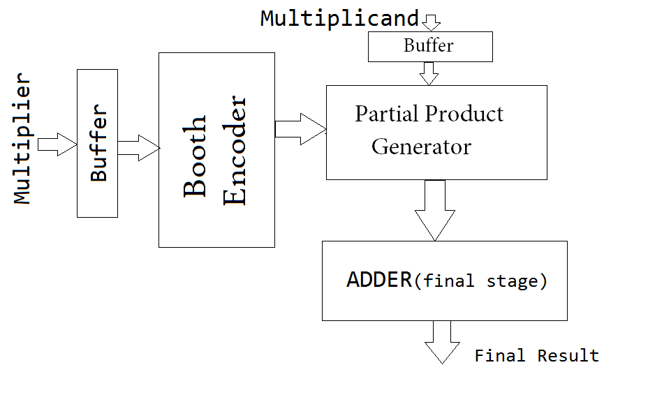
Booth Multiplier | VLSI & Embedded Projects